Audio Capture Settings
This page outlines the signal flow and settings to capture audio in the Library’s sound studios. Signal is captured from analogue sources at a sample rate of 96kHz and a word-length of 24 bits. The target preservation file format is Lossless PCM WAVE file. Each studio is equipped with two 8-channel Analogue-to-Digital converters, connected over RJ45 (Dante) or AES3, depending on the configuration.
Engineers should ensure their equipment settings match those listed below and routinely verify they are correct before undertaking transfer work.
1. Analogue to Digital Converters
1.1 Prism Sound Titan
Signal Path
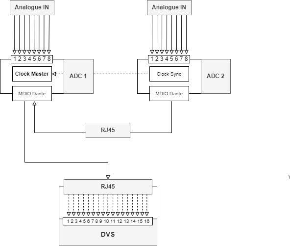
Prism Sound Titan, RJ45 connecton via Dante Virtual Soundcard
The first Prism Sound Titan in the stack is set to capture audio inputs 1-8 and is the source Master clock. The second Titan is set to capture audio inputs 9-16 and is sync’d to the first Titan. Both Titans are installed with MDIO-Dante modules connected via an RJ45 connection. All 16 inputs are passed through the first Titan and output over RJ45 to the Dante Virtual Soundcard (DVS).
The front panel of the Titan should display a green light on the following indicators:
- IP
- Line
- Master*
*Titan 1 only
1.1.1 Prism Sound Audio Control app
The Titan’s software control panel is the central tool to assign settings. Two instances of the application will open for the two connected Titans in the stack. The Titans can be identifed by their assigned name on the top bar (e.g. Dante-PS-Dante-01xxxd), to confirm their identity click Identify on the main control panel and the lights on the front panel of the selected Titan will flash.
Ensure the following settings are correct:
| Setting | Value |
|---|---|
| Device Status | Active |
| Sample Rate | 96k |
| Port Status | Master*, Slave** |
| Sync Source | Local*, PTP** |
| Dante Clock | |
| Verifile | Green |
| MDIO | Orange |
*Titan 1 only **Titan 2 only
Inputs tab
| Channels | Setting |
|---|---|
| AI 1 - AI 8 | LINE |
| +4 |
Outputs tab
| Channels | Setting |
|---|---|
| AO 1 - AO 8 | DAW |
1.2 Dante Virtual Soundcard (DVS)
DVS is a software application used to enable Dante audio data to be routed from the Titans to the PC and Wavelab. The DVS application should be set to the following:
Settings tab
| Audio Interface | ASIO |
| Audio Channels | 16 x 16 |
| Dante Latency | n/a |
| Network Interafce | Ethernet 2 |
| Options | |
|---|---|
| Buffer Size | 2048 |
| Encoding | 24 |
| Asio Latency | n/a |
1.2.2 Dante Controller
The Dante Controller is used to matrix the 16 audio channels between the Titans and PC. The routing configuration should be ordered as with the I/O 1-8 assigned to the first Titan, and I/O 9-16 to the second.
The Titan’s can be idenfified by the name assigned in the Prism Sound Audio Control app
1.3 Prism Sound Dream ADA-8XR
Signal Path
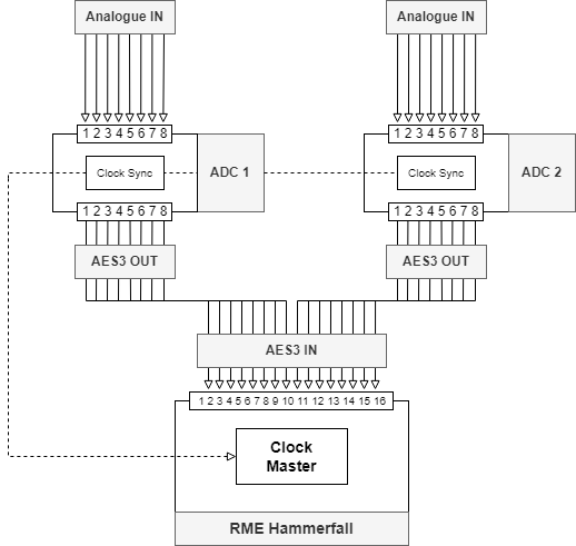
Prism Sound Dream 8XR, AES connecton via RME Hammerfall DSP
The first Prism Sound Dream ADA-8XR in the stack is set to capture audio inputs 1 - 8.
The ADA-8XR has two signal paths, Path 1 encodes analogue input and sends it to the RME Hammerfall. The settings for each path are accessed on the front panel of the interface.
1.3.1 ADC 1, Path 1
| Source | Decode | Process | Dither / Encode | Sync Source | Sample Rate | Dest |
| Analogue | 24b | Bypass | Flat | DI1 | 48k | DI1 |
| 24b | x2 |
Path 2 is set to monitor audio back from Wavelab:
1.3.2 ADC 1, Path 2
| Source | Decode | Process | Dither / Encode | Sync Source | Sample Rate | Dest |
| DI1 | 24b | Bypass | Flat | DI1 | 48k | Analogue |
| 24b | x2 | |||||
| Ext |
The second ADA-8XR in the stack captures inputs 9 - 16 and is set to sync its clock to the first ADA-8XR, which is then sync’d to the RME Hammerfall Master clock.
Path 1 should be set to the following:
1.3.3 ADC 2, Path 1
| Source | Decode | Process | Dither / Encode | Sync Source | Sample Rate | Dest |
| Analogue | 24b | Bypass | Flat | DI2 | 48k | DI1 |
| 24b | x2 | DI2 |
1.4 RME Hammerfall DSP
The RME Hammerfall is set as the Master clock for the external ADAs to sync to.
To access the RME Hammerfall Control Panel go to the Windows Taskbar and open the application labelled DSP. In the AES(1) tab set the clock Source to Internal.
| Clock Mode | – |
| Sample Rate | 96000Hz |
| Source | Internal |
Ensure the settings are correct at the start of each day before transfer. The input status will list Sync for each channel and the sample rate, if any of these values are different or do not remain static, the clock is not syncing and must be corrected.
| Input Status | – | – |
| AES 1 | Sync | 96kHz |
| AES 2 | Sync | 96kHz |
| AES 3 | Sync | 96kHz |
| AES 4 | Sync | 96kHz |
0.0 Apogee Rosetta 800 (deprecated)
Note - this interface is no longer in use
The first Apogee Rosetta 800 in the stack is set to capture audio inputs 1 - 8. The second Rosetta 800 is set to capture audio inputs 9 - 16.
The front panel settings for both interfaces are set to the following values:
| SAMPLE RATE | (WC I/O) SYNC | LOCK | SOURCE TO DIGITAL OUTS | OUTPUT RESOLUTION |
| 96 | EXT | WIDE NARROW | ANALOGUE | 24-BIT |
| AES |
2. Prism Sound Verifile Checker
Note, Verifile is only compatible with the Prism Titan
After transfer, audio files need to be validated using Verifile. Open the Verifile Checker application, select files for validation either via the Browse button or by simply dragging-dropping into the main window, click Verify to start the validation.
If a file fails validation it must be re-transferred without error.
3. WaveLab
The primary Digitial Audio Workstation (DAW) used for audio capture and editing is Steinberg’s WaveLab Pro.
The following file capture and edit settings should be applied when first setting up Wavelab and routinely verfied.
3.1 Capture
Open the Recording Dialog from the Main Audio Editor by clicking the Record button in the Transport control, click the blue audio format text to open the Audio File Format window and set the file capture settings:
| Type | Wave (Microsoft) |
| File Extension | wav |
| Audio Format | PCM (uncompressed) |
| Channels | Multi Stereo |
| Sample Rate | 96 000 Hz |
| Bit Depth | 24 |
| Meta-Data | -> Inherit from Source File |
Click Okay to save the settings.
3.2 Metadata
Files are set to embed the following metadata in the RIFF chunk of the WAVE file header:
- Name of engineer
- Capture software
- Date of transfer
To automatically write metadata to file during capture, open the Metadata window from Tool Windows > Metadata > RIFF tab > Edit and enter the following values:
| Code | Name | Value |
|---|---|---|
| IENG | Engineer | Name |
| ISFT | Originator Software | @WaveLabAndVersion@ |
| ICRD | Date | @Date12@T@Time3@Z |
Note - Date and time is formatted in SMPTE-25
Commit the changes by clicking Use as Default for New .wav Files
Embeded file metadata can be viewed at any time in the Metadata window.
3.3 File Preferences
Audio file preferences are set in the File > Preference > Audio Files > File tab, ensure the options are selected / deseleted according to the list below:
- Support RF64 File Format
- Create Optimized Audio File Headers
- Write Markers in WAV File Header (RIFF Format)
- Write Markers in WAV File Header (BWF Format)
- Write Markers in Seperate File
- Create Peak Files in an Independent Folder
- Create Peak Files When Writing Audio Files